RANCO, Low Pressure, 1/4 in Male Flare, Single Pressure Controls 2E980O101401 Grainger
View and Download Ranco O10 installation data online. SINGLE PRESSURE CONTROL. O10 controller pdf manual download. Also for: 011, O16, O20.
[DIAGRAM] Ranco Oil Pressure Switch Wiring Diagram
TYPE P32 LOW PRESSURE LIMIT CONTROL The Ranco P32 low pressure control provides freeze protection or low refrigerant protection on chillers and other refrigeration systems by sensing suction pressure. It is suitable for R-12, R-22, and R-502 refrigerants. A time delay is provided to allow for start-up in low ambient and momentary low pressure.
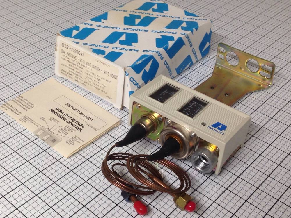
Dual Pressure Control RANCO 0121506A
Fortunately, the Ranco Oil Pressure Switch Wiring Diagram offers reliable instructions that make it easier for experienced and first-time mechanics alike to install a new switch safely. In this article, we'll discuss the features, benefits, and consider the critical steps when wiring your Ranco Oil Pressure Switch. Features and Benefits of the.

3 phase pressure switch wiring diagram
Here is a wiring diagram that I used for my Ranco Temperature Controller. I cut apart a heavy gauge extension cord to use for my wall power connection and for the wiring I used to connect to my output plug. Inside the extension cord is a ground wire, common wire and hot wire. In the diagram above I use the green wire to represent ground, the.

14 Elegant Ranco Dual Pressure Switch Wiring Diagram
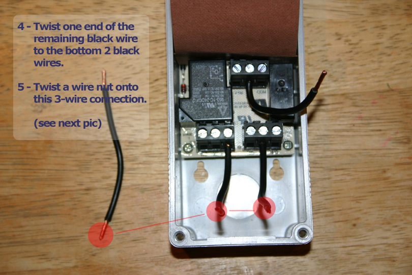
Contacts below are shown in normal run condition with oil pressure. Typical Old Copeland 3-Wire Oil Pressure Safety Control Wiring Manual reset timer contacts. Terminal 21 to 22 closed during normal run and during time-out - open on time-out. Terminals 21/24 (signal) closed after time-out. Power to Timer thru pressure switch contacts.

How To Ranco Two Stage ETC Wiring Instructions Homebrew Talk Beer, Wine, Mead, & Cider
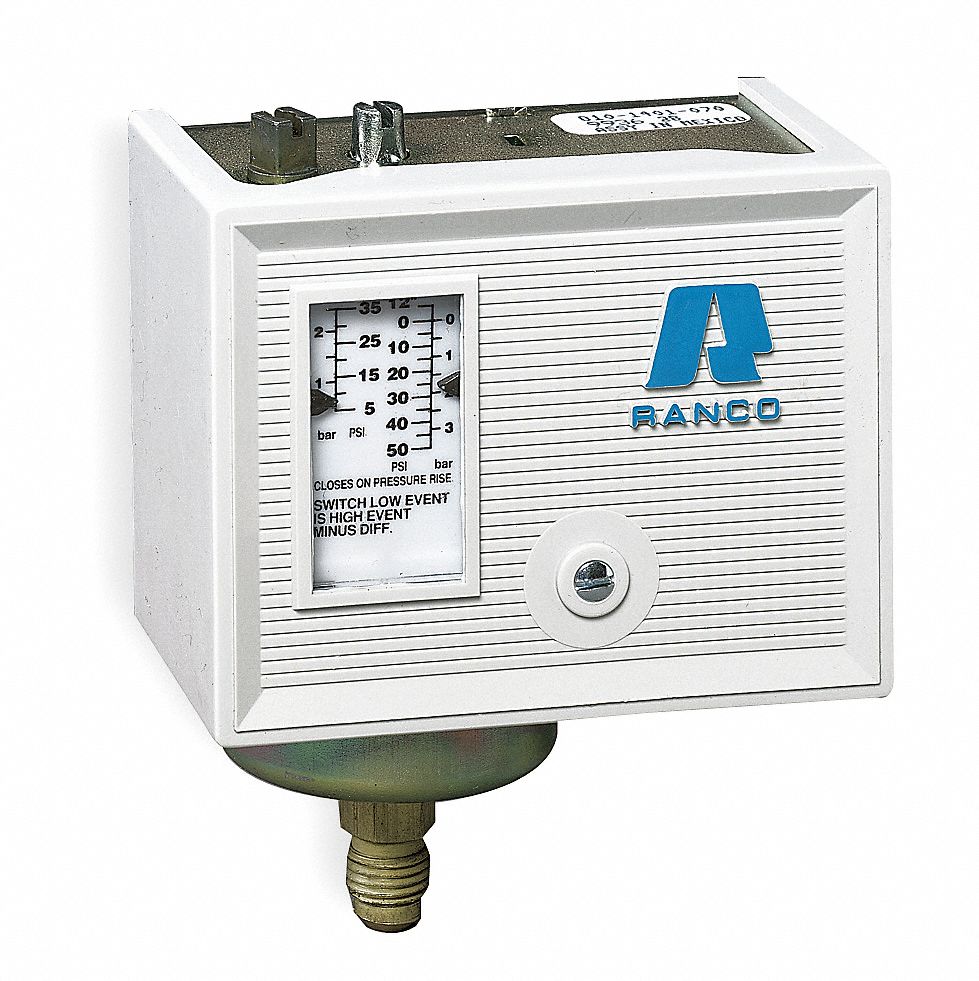
low-pressure control in one unit with a single pole, single throw (SPST) switch or a single pole, double throw (SPDT) switch. The Ranco® O Series Single Low and High Pressure Controls offer a variety of pressure ranges and switch action to provide maximum application flexibility. O12-1550-081 O16-528-081 Part Numbers Replaces

[DIAGRAM] Ranco Oil Pressure Switch Wiring Diagram
5. Replaces Ranco P30-5827 (Includes alarm wire) Carlyle® Compressors P45NCA-82C 6 6. Replaces Carlyle/Carrier® Code No. HKCA-500, 6342050 45 seconds 120/240 Manual 425 (2,390) 6.5 (45) 7 7. Switch differential is approximately 4.5 psi (34 kPa). Time delay relay energizes at 6.5 psi (45 kPa) pressure difference, de-energizes at 11 psi (76 kPa.

️Ranco Dual Pressure Switch Wiring Diagram Free Download Gmbar.co
The high pressure function overrides to open the switch as the compressor discharge pressure rises. Low Pressure (Open Low): 10" to 100 PSI, 10 PSI fixed differential, manual reset. High Pressure (Open High): 150 to 450PSI, 70 PSI fixed differential, manual reset. Capillary: 36" with 1/4" SAE flare nut. Switch: SPST. FLA: 24Amps @ 120VAC/240VAC.

Bestly Ranco Pressure Switch Wiring Diagram
The Ranco® P30 Series Lube Oil Protection Controls guard pressure-lubricated refrigeration compressors against major damage due to loss of oil pressure. This control utilizes the built-in P30 Time Delay Switch to start timing when oil pressure drops below operating requirements. The timer is designed not only to track oil pressure recovery.

Ranco Dual Pressure Switch Wiring Diagram Diagram & Schemas
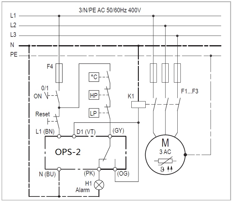
switch on pressure drop. The high pressure function. interconnected to operate a common switch. Ranco dual pressure controls are suitable for R 12, R22, and R502 refrigerants and are available with either male. CONTROL WIRING 1. Disconnect electrical power to the unit. 2. All electrical wiring should conform to the National

Pressure switch RANCO 017H4701 Double
Looking For Diagram Electrical Wiring? We Have Almost Everything On eBay. Fast and Free Shipping On Many Items You Love On eBay.

️Ranco Dual Pressure Switch Wiring Diagram Free Download Gmbar.co
The ETC two stage can be programmed in seven simple steps using the LCD display and the three keys on the face of the control. Step 1- To start programming, press the SET key once to access the Fahrenheit/Celsius mode. The display will show the current status, either F for degrees Fahrenheit or C for degrees Celsius.
How To Ranco Two Stage ETC Wiring Instructions Homebrew Talk Beer, Wine, Mead, & Cider
A70 Series Four-Wire, Two-Circuit Temperature Control 55. Typical Wiring Diagram and Electrical Ratings for Line Voltage 90 T23 Series Fan Coil Thermostat (with Fan and System Selectors) 92. P100 Series Encapsulated Pressure Switches 114 Refrigeration Products Catalog 4. Contents

How To Ranco Two Stage ETC Wiring Instructions Homebrew Talk Beer, Wine, Mead, & Cider
Manual reset O16 low pressure controls have a scaleplate that indicates the pressure at which switch terminals 2-3 will lock setting before the control can be reset. High pressure controls which are used to cut-out the compressor on pressure rise should normally be set not higher than the values shown below: Volts FLA LRA NIA PD VA 32 9.3 93 72.
Ranco wiring REEF2REEF Saltwater and Reef Aquarium Forum
Ranco O and G series pressure controls are designed to switch electrical loads such as contactors, relays, fans and motors in HVAC and Commercial applications in response to changes in sensed refrigerant pressure.. Ranco O Pressure Controls Australia 1.10 MBPDF. Instruction RANCO O16 O17 344.91 KBPDF. Kirby looks beyond the basics of.

Bestly Ranco Pressure Switch Wiring Diagram
and 10 volts = 220°F. See figure 8 for wiring information and figure 3 for location of the entry hole. The reference for this output is designated by the "-" symbol on the wiring diagram. The output signal is designated by the "+" symbol. Figure 4: Typical Line Voltage Wiring Diagram. Figure 5: Typical Wiring Diagram for 240 VAC Power Input and
